1.Warranty time: 1 year
2.Delivery time: 3-5 days
3.Product quality: new or discontinued second-hand
1. We are a global trading company, we have a large stock of spare parts, we also produce energy storage batteries
2. Our main sales products are industrial automation control equipment accessories, such as: controller board, processor module, communication module, input and output module, power module (various circuit boards and cards), touch screen, servo driver, servo motor, sensor, cable......
3. We can not only provide new products, but also supply cold and discontinued spare parts, all the discontinued parts will go through strict testing to ensure the reliability of product performance, so that customers can buy and use at ease
4. For more information, please contact us: Contact: Amy | Email: saul01@qq.com | Tel(WhatsApp/Wechat): +86-15359298283

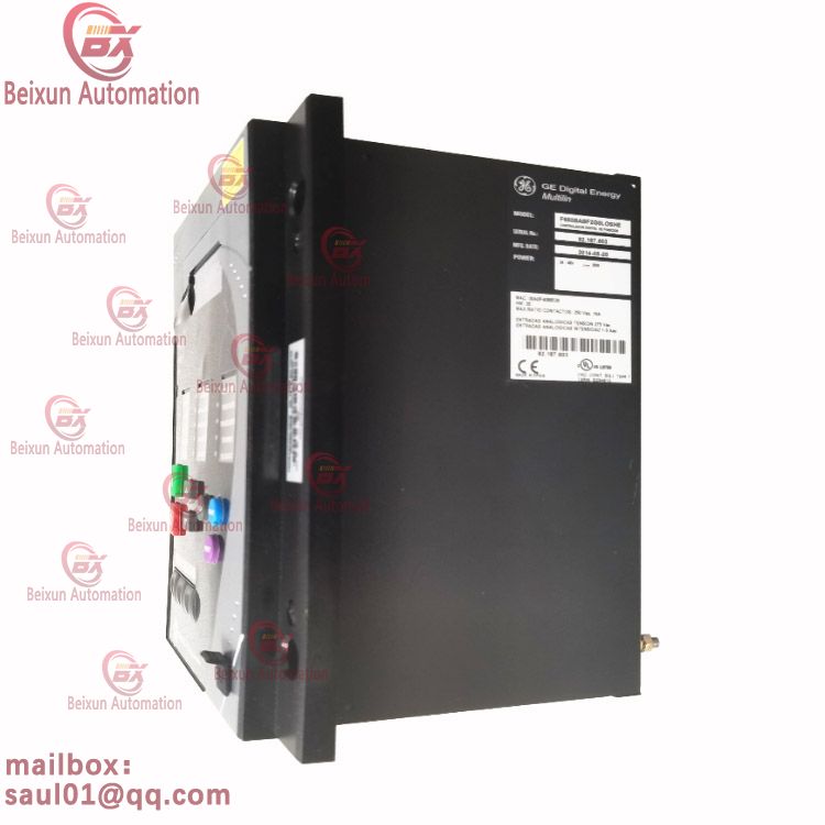
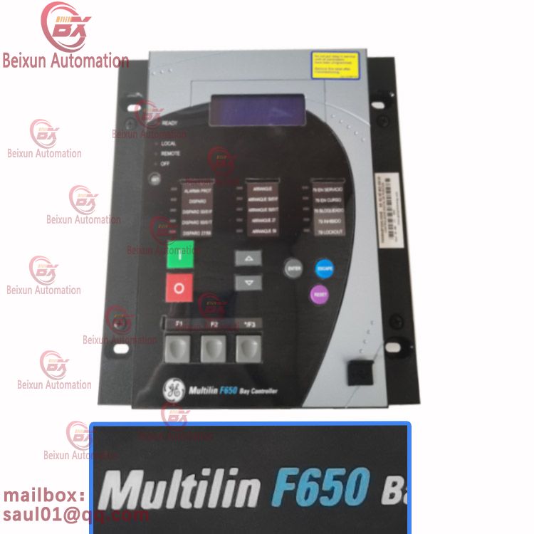
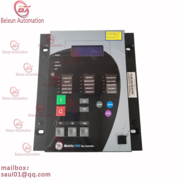
GE F650BABF2G0LOSHE Feeder protection equipment The F650BABF2G0LOSHE Of PLC And Configure Software In Minitype Automated Storage System Is Introduced In This Paper,Citing The FX-2N Series Programmable Controller
The relay is manufactured by General Electric (GE) and has a unique part number, F650BABF2G0LOSHE. It is available in different models, and the specifications of the relay may vary depending on the model. The relay has the following basic features,

Brand:GE
Model:F650BABF2G0LOSHE
Part No:
Product Name:Feeder protection equipment
F650BABF2G0LOSHE
DISCONTINUED BY MANUFACTURER
FEEDER MANAGEMENT RELAY
BASIC DISPLAY
REAR SERIAL COMM - REDUNDANT RS485
REAR ETHERNET COMM - 10/100 BASE TX
19" RACK
24-48 V DC

The replace a relay, it is necessary to remove the GE Simplex Trip Board DS200TCTGG1AFF from the drive. Communicate with an engineer or installer who is familiar with the installation of the drive and is experienced with the power supplies connected to the drive. Disable the power supplies by disconnecting the fuse or by other means as required. Use a testing device to test the interior of the drive for electric current, before you continue. Disconnect the cables from the board and diagram the locations of the cables so that you can connect the cables to the right connectors when you reinstall the board.