1.Warranty time: 1 year
2.Delivery time: 3-5 days
3.Product quality: new or discontinued second-hand
1. We are a global trading company, we have a large stock of spare parts, we also produce energy storage batteries
2. Our main sales products are industrial automation control equipment accessories, such as: controller board, processor module, communication module, input and output module, power module (various circuit boards and cards), touch screen, servo driver, servo motor, sensor, cable......
3. We can not only provide new products, but also supply cold and discontinued spare parts, all the discontinued parts will go through strict testing to ensure the reliability of product performance, so that customers can buy and use at ease
4. For more information, please contact us: Contact: Amy | Email: saul01@qq.com | Tel(WhatsApp/Wechat): +86-15359298283
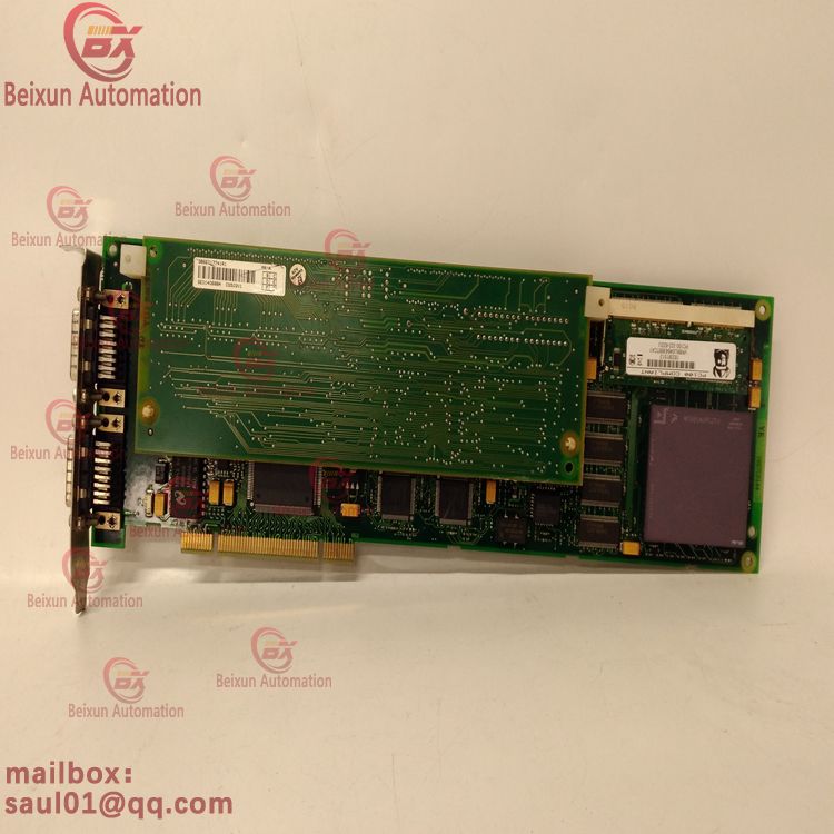
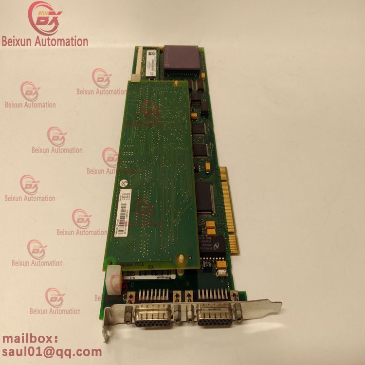
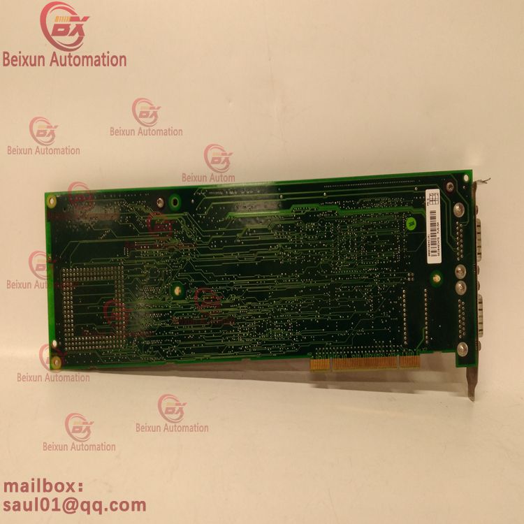
ABB power controller module PU515A 3BSE032401R1

ABB power controller module PU515A 3BSE032401R1v

ABB power controller module PU515A 3BSE032401R1

1.- Individual amplifier not coupled through the DC bus link circuit (DC+, DC-) When the average power or peak power of the energy feedback from the motor exceeds the preset level of the brake rated power, then the servo amplifier generates a warning "n02 brake power exceeded" and the brake circuit is turned off. The next internal check of the DC bus link voltage (a few milliseconds later) detects an overvoltage, the output stage turns off, and displays the error message "Overvoltage F02" (page 112). BTB/RTO contacts (terminals X3/2,3) will open simultaneously (page 94)
2.- Several servo amplifiers coupled via a DC bus link (DC +, DC -) With built-in braking circuits, several amplifiers (even with different current ratings) can be operated via a common DC bus link without any additional measures. Combined (peak and continuous) power of all amplifiers is always available. This overvoltage is disconnected as described in 1. (above) has the lowest turn-off threshold (caused by tolerances) for the amplifier. The technical data of the brake circuit depends on the amplifier type and the supply voltage situation, see the table on the next page.
On and Off Behavior This chapter describes the on/off behavior and procedure of the S300. Stop operation or stop emergency.
UFC719AE101 3BHB003041R0101 3BHB00072R0101 UFC718AE101 HIEE300936R0101 UCD240A101 UBC717BE101 3BHE021887R0101 UCD208A101 3BHE020018R0101 UCD224A102 3BHE023681R0102 UAD142A01 3BHE012551R0001 UAC389AE02 HIEE300888R0002 UAC389AE01 HIEE300888R0001 SYN5202-0277 3BHB006715R0277 SYN5201A-Z,V277 3BHB006714R0277 SYN5201A-Z V277 3BHB006714R0277 SYN5200a-Z, V217 SYNCHROTACT5 3BHB006713R0217 PU515A 3BSE032401R1 PU517 UNITROL 1020 3BHE030579R0003
Servo amplifiers use integrated circuits to detect if there are one or more input phase (power feed) faults. Use the setup software to set the behavior of the servo amplifier: under Input Phase Loss Response (PMODE) on the basic setup screen, select: If the higher level control system wants to stop the driver, issue a warning: If the input phase is missing and the motor current is limited, output a warning n05. This servo amplifier is not disabled. The advanced control system can now selectively end the current loop or start stopping the drive. Thus, the error outputs the message "MAINS BTB, F16" on the digital output of the servo amplifier, and is evaluated for example by the control system. If the servo amplifier wants to stop the driver, an error message is displayed: If the input phase is lost, an error message F19 is output. The servo amplifier is disabled and the BTB contact is disconnected.
Behavior when the undervoltage threshold is reached If the undervoltage threshold in the DC bus link is insufficient (the threshold depends on the type of servo amplifier), the error message "Voltage is too low, F05" is displayed. The drive response depends on the ACTFAULT/STOPMODE setting. Behavior when the "lock" function is enabled Servo amplifiers with the hold brake function enabled have a special procedure for turning off the output stage (page 29). Removing the ENABLE signal triggers electrical braking. As with all electronic circuits, general rules apply when an internal "lock" module fails. The use of a bracket to bring the motor to a standstill to brake in a functionally safe manner also requires an electromechanical "close" contact for the holding device and a restraining device for the brake.
stop
The stop function is used to shut down the machine during normal operation. The stop function is defined by IEC 60204. Category 0: Shutdown of drive machinery by immediately shutting down the right energy supply (i.e. uncontrolled shutdown); This can be done with the built-in STO feature (see page 37); Class 1: Controlled shutdown, thus providing energy to the drive maintenance machine to perform shutdown, and energy supply is interrupted only when shutdown is complete; Class 2: Controlled shutdown, thus providing energy for the drive machine to be maintained. The stop category must be determined through a risk assessment of the machine. In addition, appropriate means must be provided to ensure reliable closure. Class 0 and Class 1 stops must operate independently of the mode of operation, where class 0 stops must have priority. The stop function must be disconnected from the appropriate circuit by the implementation and have a higher priority than the assigned start function. Protection and locking must be provided if necessary. If applicable, the stop function must signal its status to the control logic. The operation of resetting the stop function must not cause a dangerous situation.
Emergency Stop The emergency stop function is used to shut down the machine as quickly as possible in a dangerous situation. The emergency stop function is defined by IEC 60204. The principles and functional aspects of emergency stop devices are defined in ISO 13850. The emergency stop function will be triggered by a person's manual action. It must be fully functional and readily available. The user must immediately understand how to operate this mechanism (without reference to resources or instructions). The parking category of emergency parking must be determined by a risk assessment of the machine. In addition to stopping requirements, emergency stopping must meet the following requirements:
Emergency shutdown The emergency shutdown function is used to shut down the power supply machine. This is done to prevent the user from any risk of electrical energy (such as electrical shock). The functional aspects of emergency shutdown are defined in IEC 60364-5-53. The emergency shutdown function will be triggered by a person's manual action. The results of the machine risk assessment determine the need to shut down the function in an emergency. The emergency shutdown is accomplished by turning off the power from the electromechanical switchgear. This will cause class 0 to stop. If in the application, then the emergency shutdown function must
Advantages of restart Lock STO: - Since the main power line is still active, the DC bus link is still charged - only switching low voltage, so no contact wear - little cabling safety features are required The STO can be controlled via secure external controls (semiconductor output or driven contacts). The security concept is certified. Safety circuit concept for safety functions According to IEC, "Safe torque off" in the servo amplifier S300 applies to SIL CL 2 62061 and PLDS. UNS0119A-Z,V1 3BHE030579R0001 UFD203A101 3BHE019361R0101 UFC911B108 3BHE037864R0108 UFC762AE101 3BHE006412R0101 UFC760BE43 3BHE004573R1043 UFC719AE101 3BHB003041R0101 3BHB00072R0101 UFC718AE101 HIEE300936R0101 UCD240A101 UBC717BE101 3BHE021887R0101 UCD208A101 3BHE020018R0101 UCD224A102 3BHE023681R0102 UAD142A01 3BHE012551R0001 UAC389AE02 HIEE300888R0002 UAC389AE01 HIEE300888R0001 SYN5202-0277 3BHB006715R0277 SYN5201A-Z,V277 3BHB006714R0277
Use as directed
Security Features STO is specifically designed to provide functional security by preventing system reboots. In order to achieve this functional safety, the wiring of the safety circuit must comply with the safety requirements of IEC 60204, ISO 12100 and IEC 62061 SIL CL2, respectively, ISO 13849-1 PLd. If the STO is automatically activated by the control system, ensure that the output monitors the control device for possible failures. 6.9.4 Disable Use The STO feature must not be used if the drive is inactive for the following reasons
The reason:
- Cleaning, maintenance and repair operations, not working for a long time: in this case, the entire system should be passed by personnel, and fixed (main switch).
Emergency shutdown: The power contactor must be turned off (through the emergency shutdown button).
wiring
When using STO wiring leads outside the control cabinet, the cables must be laid durable (strong), protected from external damage (such as laying in cable ducts), in separate sheathing or protected separately by a ground connection. The wiring in the required housing must meet the requirements of IEC 60204-1.
Electrical installation guide
Correct wiring is the basis of reliable operation of the servo system. Lay out power cables and control cables. We recommend at least a distance of 200mm. This improves anti-interference. If a motor power cable is used, a core for brake control is included, which must be shielded separately. Ground both ends of the shield. Ground all shields (low impedance) in large areas, using metallized connector housing or shield clamp whenever possible. For connection technology, see page 52. The feedback line may not be extended because the shielding will thus be interrupted and signal processing may be interfered with. The line brake resistor between the amplifier and the outside must be shielded. Install all power cables with sufficient cross sections, according to IEC 60204(page 28), and use the required cable material (page 53) to reach the maximum. Cable length.
Each SM128V occupies a single slot in the VME rack.
1. Unwrap the card carefully. Use a grounding wire or release any static electricity to remove from yourself before touching the card.
2. Place the card soldered side down on a uniform, clean, dry surface to set the DIP switch as required.
3. Close the VME bus rack.
4. Hold each finger of the card with two sliding elements (handles) between your thumb and index finger.
5. Carefully slide the card into the appropriate slot of the VME system.
6. Secure the two guide pins at the rear before sliding the card into the end
The sides of the front panel slide into dedicated holes in the rack.
7. Unless done, lift the lower and upper sliding elements (handles) separately until they click.
8. Press your thumb against the front panel and push the card to the end.
9. Secure the card to the rack using the two screws at the upper and lower ends of the front panel. The GE90/70 system rack does not have an opening for the SM128V board guide pins. If this fact is not taken into account when ordering the card, the guide pin must be removed before the card is installed. SYN5201A-Z V277 3BHB006714R0277 SYN5200a-Z, V217 SYNCHROTACT5 3BHB006713R0217 PU515A 3BSE032401R1 PU517 UNITROL 1020 3BHE030579R0003 UNS0119A-Z,V1 3BHE030579R0001 UFD203A101 3BHE019361R0101 UFC911B108 3BHE037864R0108 UFC762AE101 3BHE006412R0101 UFC760BE43 3BHE004573R1043 UFC719AE101 3BHB003041R0101 3BHB00072R0101 UFC718AE101 HIEE300936R0101 UCD240A101 UBC717BE101 3BHE021887R0101 UCD208A101 3BHE020018R0101 UCD224A102 3BHE023681R0102 UAD142A01 3BHE012551R0001 UAC389AE02 HIEE300888R0002 To remove the board from the VME rack, perform the following steps:
1. Power off the VME rack.
2. Loosen the screws on the front panel.
3. Press the two sliding elements (handles) open. This will release
Card in backplane connector.
4. Remove the card from the slot.
Fiber Optic Connectors TX and RX(5)(6)
Channel 1 is a two-way communication interface port with compatible devices via TX and RX. Both ports use standard ST connectors. TX implements a fiber optic transmitter, while RX implements a fiber optic receiver.
Fiber Optic connector TX(10) Channel 2 Port for one-way communication with compatible devices through the TX interface. This port uses a standard ST connector. TX implements fiber optic transmission of channel 2.
RJ11 Connector Channel 1(11)
Channel 1 can send data one-way to a single ibaPCMCIA-F device. This port uses the dedicated serial cable included with the PCMCIA-F. The transmission data is synchronized with optical channel 1. RJ11 Connector Channel 2(12) Channel 2 can send data unidirectionally to a single ibaPCMCIA-F device. This port uses the dedicated serial cable included with the PCMCIA-F. The transmission data is synchronized with optical channel 2.
On-board DIP switch The DIP switch is located at the lower part of the board. They are used to set interrupts, data formats, and memory addresses. The service interface (D-sub 9) load firmware is also located in this area.
ABB power controller module PU515A 3BSE032401R1